JMRI: Aspect Signaling
Controlling model signals in a prototypical manner
 Protoypical signal systems present "Aspects" to the engineer to tell him how to run his train. The
"Stop" aspect, for example, is pretty simple: "Stop the train". The "Approach medium" aspect
indicates something more complicated: "Proceed approaching next signal at medium speed". Each
aspect has an associated "indication", which is usually codified in a railroad's Rule Book.
Protoypical signal systems present "Aspects" to the engineer to tell him how to run his train. The
"Stop" aspect, for example, is pretty simple: "Stop the train". The "Approach medium" aspect
indicates something more complicated: "Proceed approaching next signal at medium speed". Each
aspect has an associated "indication", which is usually codified in a railroad's Rule Book.
The picture to the right shows an example, Rule 282 from the 1946 AAR rule book (Aspect: Approach Medium).
JMRI Support for Aspect Signaling
A collection of plain instructions let you set up Signaling in 7 Quick Steps.
Aspect Signaling is supported in JMRI using three of the Signaling Tools:
-
Signal Mast objects represent an entire
signal with one or more Signal Heads. A Signal Mast can operate all its Heads, as
required to do full prototypical signaling based on aspects. When its Aspect is set to
e.g. "Approach medium", JMRI handles the layout communication needed to make the signal
on the layout display the right colors.
 Signal Masts are configured through
the Signal Mast
Table. You add new ones with the "Add..." button below the table, which takes you to
the "Add Signal
Mast" window. There you specify what kind of signaling system is to be used (see
the list below), the specific signal type eg. "double searchlight"
or "double head dwarf" and which Signal Heads this Mast is going to drive.
Signal Masts are configured through
the Signal Mast
Table. You add new ones with the "Add..." button below the table, which takes you to
the "Add Signal
Mast" window. There you specify what kind of signaling system is to be used (see
the list below), the specific signal type eg. "double searchlight"
or "double head dwarf" and which Signal Heads this Mast is going to drive.
You can add a Signal Mast icon in the Panel Editor by right clicking at any location and choosing "Add item > Signal Mast".
In Layout Editor enter the Signal Mast address and shift click on a turnout or anchor point on the panel where you want to place a Signal. The Signal Mast icon will display the images specified in the appearance definition for that particular Signal Mast type and system. The Signal icons displayed on your panel are part of a Signal System and they can't be changed individually by the user like Turnout icons.
Image on the right: Rule 281 Signal Icons from the AAR-2 Signal System.
- Signal Groups are used to define a
number of Signal Heads, where only one Signal Head can be illuminated at any given time,
depending upon the state of the associated Signal Mast and a set of conditions.
Signal Groups would be used where additional indicators are used to support the main Signal Mast, such as Junction, Route or Speed displays. These indicators provide additional information to the driver (US: Engineer) that is not given by the main Signal Mast. Such indicators are frequently seen in European and UK signaling. - The Signal Mast Logic tool allows
the Signaling Logic to be built up as pairs of conditionals between Signal Masts on the
layout. The Signal Mast Logic will use the states of Blocks, Turnouts, Sensors and adjacent
Signal Masts to determine what Aspect a Signal Mast should be displaying.
If the layout has been drawn up using the Layout Editor and Signal Masts have been placed on the panel using the various tools, then it is possible for all the Signal Mast Logic to be dynamically built, with little user intervention. For panels created with Control Panel Editor some of this information has to be entered manually.
Signal Head objects in JMRI are not aware of their position on a mast and the Signaling System they are part of, so as individual objects they can't show Signal Aspects. Individually they can only be set to specific Appearances (colors), either from the Signal Head Table or via Logix.
How does it work?
In short, a set of files for the selected Signaling System contains the basic code to
determine which combinations are available in the Signal Mast
Logic tool.
In the xml/signals directory located in the JMRI program directory, there is a directory for
every Signaling System that has been defined, with one "aspects.xml" file which lists all of
the possible Aspects plus a number of "appearance..." files (i.e.
appearance-one-searchlight.xml), each of which describes the possible Aspects based
on one Signal Mast type. These essentially say "if the next signal has an 'x' aspect, then
the current one needs to show a 'y' aspect" (more
details).
The Signal Mast Logic table is then used to check which Signal Mast pairs are active in the
Signal Mast Logic and whether the Aspect should not be 'Stop'. This is done by
looking at Turnout positions (if applicable), Block occupancy and - possibly - Sensors. On
the Signal Masts tab you might even specify additional Signal Masts to watch, e.g. for an
Interlocking. For any Signal Mast, there can be 1 to n destination Signal Masts, one of which
is active based on the positions of Turnouts connecting the protected Blocks.
If everything is OK, then the appropriate "appearance..." file for this Signal Mast type will
be used by the Signal Mast Logic to assign a new Aspect based on the Aspect of the next
Signal Mast.
This covers the basic workings in a very high level overview. (Thanks to Dave Sand)

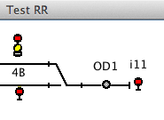
Signal 4B showing the "Stop" Aspect when sensor OD1 is Active (at left) and "Approach Diverging" when the block is empty (at right).
Available Signaling Systems
JMRI users have provided signaling systems for Basic, AAR-1946, BR-2003 and many more. The complete list is at https://www.jmri.org/xml/signals/.
To create your own Signaling System Definition follow these Instructions. If you do create a new definition for another prototype railroad or era, after testing please contribute it back to the JMRI project so we can distribute it with future releases of the project for others to use. Like Decoder Definitions in DecoderPro, the more Signal System Definitions we have, the more useful the program becomes, and the more people spend time to improve it. We all win that way!
Code Access to Aspect Information
Logix
Signal Masts can be both tested (in Conditionals) and set (in Actions) via Logix. When you're editing a Logix Conditional or Action, you have to type the Signal Mast name and hit enter/return so that the program can look up the available Aspects for that particular Signal Mast.
Scripting
A program (in Java or Python) can get access to Aspect information in two ways. If the code has a reference to a specific Signal Mast "m", it can use
m.getValidAspects()to get the list of aspect names that this Signal Mast can display. The program can then access the Signal System definition with
SignalSystem sys = m.getSignalSystem()and then enquire about properties of the aspect:
sys.getProperty("Clear","speed");
where the first argument is the aspect name (use, for example, m.getAspect() to
obtain the current one on the mast) and the second is a specific property. Properties can be
defined programmatically via e.g. m.setProperty("Clear","speed","69"); or get loaded
automatically from elements in the aspect.xml file that
defines the specific signal system.
In addition to the global properties for an Aspect, there can also be local properties to a specific Signal Mast type. An example of this is the default icon image: The image for a two-head Signal Mast is different from that for a one-head Signal Mast, even if they both represent "Clear".
To get those:
m.getAppearanceMap().getProperty("Clear","imagelink");
In words, this is saying "Get the Appeance info for this Signal Mast, and then check the
imagelink property of the Clear aspect".
Alternatively, if you know the name of the Signal System in use, a program can access it directly via the InstanceManager:
SignalSystem sys = InstanceManager.getDefault(SignalSystemManager.class).getSystem("basic");
Back to the Signaling main help page.