JMRI: Simple Signal Logic
Contents
The documentation below describes Signaling with JMRI using an older tool, SSL, and discusses how to set up basic signaling situations with it.
Introduction
Simple Signal Logic (SSL) provided the first method to enable the rapid setup of basic Automatic Block Signaling (ABS) style signaling in JMRI. For more complex operations beyond the capability of SSL refer to the newer and preferred method of Signal Mast Logic on the Signaling main help page. Note that SSL ignores any Signal Mast objects and only drives individual Signal Heads.
Don't use the SSL Tool when you have already built Signal Masts and the more advanced Signal Mast Logic in the same Panel/Configuration file.
Much of basic ABS signaling can be boiled down to "a Signal Head goes red when a train can't safely enter the block it protects; it goes yellow when the block following the protected block can't be entered". Although that's a simplification, it can serve as a powerful starting point for understanding signaling logic.
The SSL user interface was designed to be user friendly to all users with basic
familiarity with JMRI. SSL provides a means for setting up basic signals in an intuitive
manner, without the user having to be familiar with all of the logic necessary to account for
the different Signal Aspects. 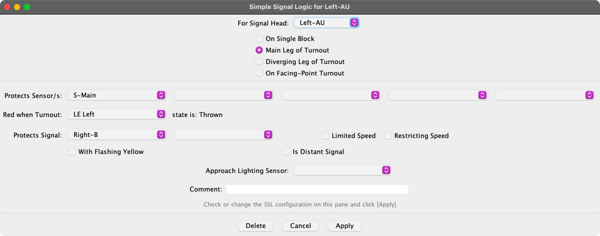
The Simple Signal Logic Tool allows you to configure JMRI to use a basic ABS type of logic to set the appearance of Signal Heads. The fields will vary based on the the selected option. Using the SSL Tool, you enter information for each Signal Head on:
- For Signal Head: The Signal Head being driven.
- Protects Sensor/s: Which sensors (occupancy detectors) cover the block immediately past the signal. When any of these sensors show "active" the Signal Head will be set to red.
- Red When Turnout: If the block contains a Turnout, pick or enter the Turnout System Name and use the selection buttons to choose whether you're entering the Closed or Thrown leg. The Signal Head will be set to Rred whenever the turnout is set against this track.
- Protects Signal: The next Signal Head that the train will reach; this Signal Head will be set Yellow if the next signal head is red.
- With Flashing Yellow If the checkbox is checked, the Signal Head will be set flashing yellow (JMRI will alternate between Dark and Yellow) if the next protected signal head is yellow, thereby giving four-block signaling.
- Limited Speed If this checkbox is checked, this Signal Head will be set to Yellow as the least restrictive Aspect.
- Restricting Speed If this checkbox is checked, this Signal Head will be set to Flashing Red as the least restrictive Aspect.
- Is Distant Signal If this checkbox is checked, this Signal will be set to the most restrictive aspect of either this Signal Head or the next protected Signal Head.
- Approach Lighting Sensor: The sensor that controls whether this Signal Head is lit or not. Only the actual hardware Signal Head on the layout will go dark. Panel indicators will show the normal signal Appearance. Leave this entry blank to always show Lit.
- Facing Point Turnout The Signal Head is located on the single track side of the Turnout, facing a choice of two or more tracks in the direction of travel.
- Trailing Point Turnout The Signal Head is located on the double track side of the Turnout, facing a single track in the direction of travel.
The case of a facing point turnout which leads to two different "Protected Signals" is also covered. If a single Signal Head is used to control both branches, then choose "On Facing-Point Turnout". If a different Signal Head will control each route, then simply choose "Main" or "Diverging" leg of turnout, as required for each one.
Pause your mouse over any entry or item in the SSL creation pane for a brief "tooltip" help reminder.
Use the Apply button to create a new SSL defintion or update an existing defintion. The Delete button will remove the SSL definition.
It's clear that SSL won't cover complicated interlockings nor will it cover the speed-signaling seen on some prototypes. However, when combined with the logic capabilities of JMRI Routes and Logix, SSL can be used to create a CTC panel, as Bob Bucklew shows on his web site.
Getting Started
Follow these steps to create your first JMRI Signal and become familiar with the SSL user interface. As a starter this example defines just one "virtual" Signal Head that doesn't really exist on the layout, so it can work with any kind of layout hardware. See the Signaling main help page for information on how to set up your own signals.
- Select Signal Heads in the PanelPro Tools > Tables > Signals menu.
- In the Signal Head Table window that appears, click the Add... button to begin defining a new signal head.
- In the Add New Signal Head pane that appears, choose the "Virtual Signal" type.
- Enter a system name such as "IH1000".
- Click Create to enter this head into the Signal Head Table.
- Enter all the Signal Heads that you will be using for this test, using different names. The actual name doesn't matter, they just have to be different.
- Now select Simple Signal Logic... in the Tools menu.
- Fill in the various entries to match your signal's requirements as previously shown.
- Click Apply to make this entry active.
- Be sure to save your work.
You have just created an SSL entry to control a Signal Head. It's as simple as that. It
took you more time to read this tutorial than to create your first SSL entry.
The following example would allow you to build actual Simple Signal Logic for signals
connected to a specific kind of DCC system:
- Select Tables > Turnouts in the Tools menu.
- Check to be sure that the outputs (Turnout addresses) that will control your Signals Heads are in the Turnout Table. If not, click the Add... button at the bottom of the Turnout Table.
- In the Add New Turnout window that appears, enter a System Name, (e.g. "LT1") and
"test" for User Name, then click Create.
Note: All System Names of JMRI objects must follow the JMRI Naming rules, starting with a capital prefix for the DCC connection type (e.g. "L" for LocoNet) followed bij a capital T in the case of Turnouts and the actual hardware address of the Turnout. - Clicking on the corresponding Closed/Thrown entries in the Turnout Table should now cause your Signal Head to change state.
- Select Signal Heads in the Tools > Tables > Signals menu.
- In the Signal Head Table window that appears, click Add... to begin defining a new Signal Head.
- In the Add New Signal window that appears choose the correct signal type to match your hardware. The required item boxes will appear.
- Enter a System Name, for example "LH152". Note: Signal Head system names must start with the connection prefix plus "H" for Head (i.e. CH, IH, LH, NH, XH, etc.) and be followed by the hardware address ("number") of the Signal Head.
- Next pick or create one or more Turnouts that will control this Signal Head. Note: In the case of SE8C connected signals, just enter the first Turnout number of each pair. The second Turnout number is automatically known.
- Click Create to enter this head into the Signal Head Table.
- Enter all the Signal Heads that you will be using.
- Now select Simple Signal Logic... in the PanelPro Tools menu.
- Fill in the various entries to match the requirements of your first signal as previously shown.
- Click Apply to make this entry active.
- Repeat steps 13-14 for each of your Signal Heads.
- Be sure to save your work. See Loading and Storing Your Work.
More on SSL
- Check out the Simple Signal Logic example.
- Backgrounds on SSL